One of the topic of the DAF group of the University of Naples is WINGLET DESIGN.
An in house MATLab code allows the design, analysis and optimization of winglets for any aircraft category!
The developed tool is integrated with a panel code aerodynamic analysis and optimization algorithms.
Several winglets have been designed during the last years on light, commuter and turboprop aircraft. During 2012 an interesting
conceptual design for an inflatable adaptive wing-tip device on a long range turbofan aircraft has been carried out. This research
is still in progress.
Light aircraft Winglet
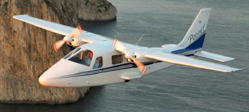
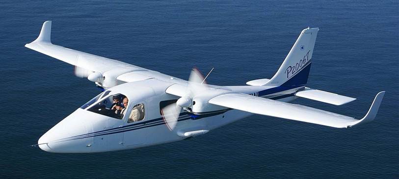
The first wing-tip device designed at ADAG group was during 2006 on the TECNAM P2006 Aircraft.
The first prototype of the aircraft used for flight tests was characterized by a wing span of 11.2 meters and a wing area of S=14.74 m2
and by an aspect ratio AR=8.46. Several tests were performed to highlight level flight and climb performances.
In OEI conditions performance were unsatisfactory and it was decided to modify aircraft wing tip installing winglets.
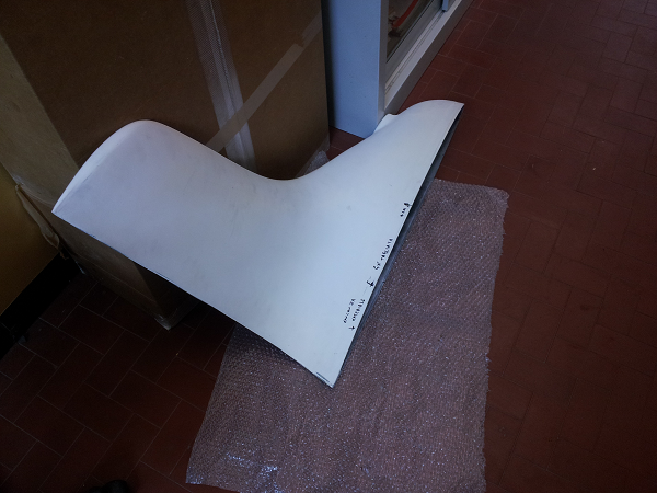
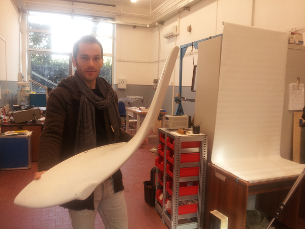
The winglets (designed at Department of Aerospace Engineering by the Authors) were designed to increase aircraft’s induced
drag factor with a very low penalty in level flight performances. The wing wetted area was maintained the same and after winglets installation the aircraft was
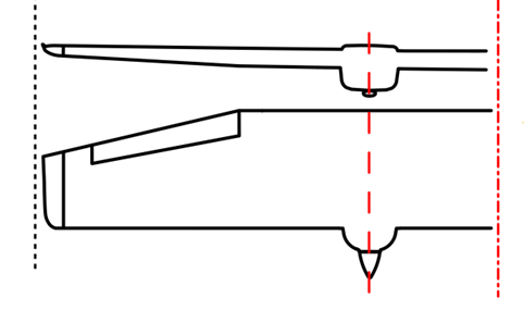
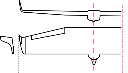
characterized by an increased wing span (only 0.20 meters higher, 11.4 instead of 11.2 meters), about the same wing planform area (14.76 m2) and an increased wing AR=8.76
(see also figure below). Calculations performed in the design and optimization of the winglet (performed through the use of a panel method code) showed an increment of induced drag
factor due to the winglet of about 0.09. In addition, wind tunnel tests were performed on a semi-model of elliptical wing with the designed winglet installed
and a measured increment of the induced drag factor of 0.08 has been noticed. The winglet height was chosen about 10% of the wing semi-span (0.6 meters) and was limited
to avoid excessive increment of wing bending moment at the root(the wing structure was not modified) and also to limit aerodynamic load on the winglet and weight
of the winglet itself. The winglets were manufactured in composite material (as the wing tip of the original prototype), installed on the aircraft (see also figure below)
and the aircraft maximum take-off weight was modified and increased to 1180 kg.
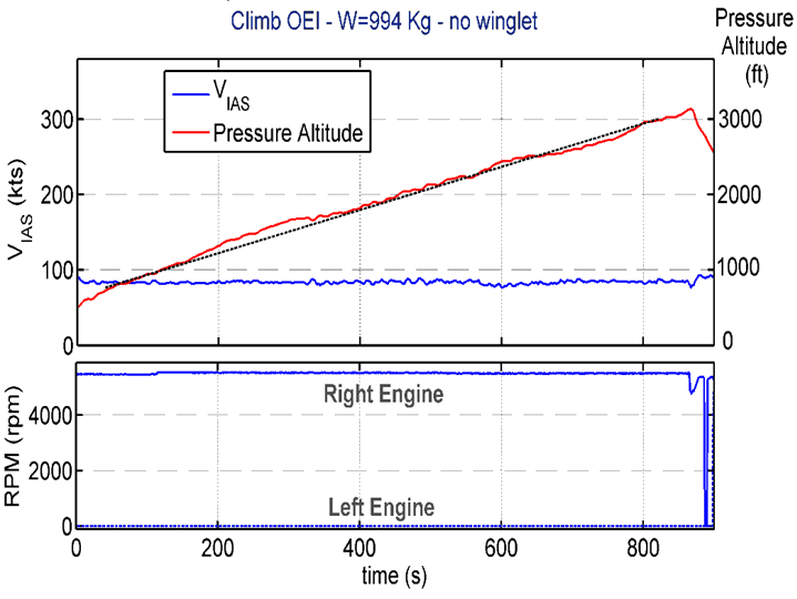
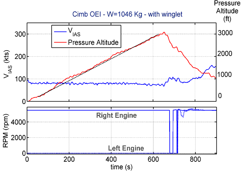
After winglet installation, OEI climb tests has been repeated and OEI max rate of climb was measured. Figures below show
time-histories of OEI climb before and after winglet installation. The winglets have determined a noticeable increase
of climb characteristics in OEI conditions. The maximum rate of climb increased from 170 to 300 ft/min.
Commuter aircraft Winglet
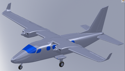
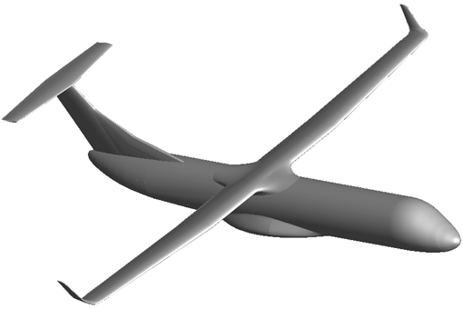
Winglets have been designed for the new TECNAM P2012 Traveller commuter aircraft. This wing tip device has been designed mainly
to improve the climb performance in one engine inoperative conditions, without affect significantly cruise performances.
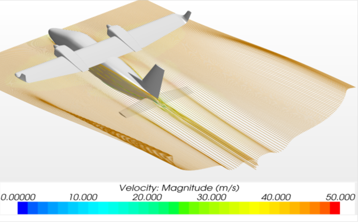
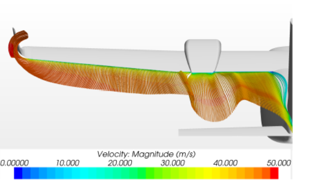
Winglets effect on wing span load, longitudinal stability and lateral-directional stability has been carefully analyzed.
Turboprop aircrat Winglet
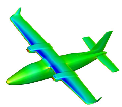
Winglets on turboprop aircraft have been designed.
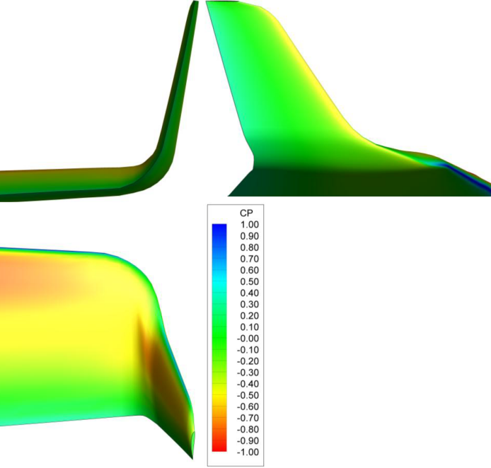
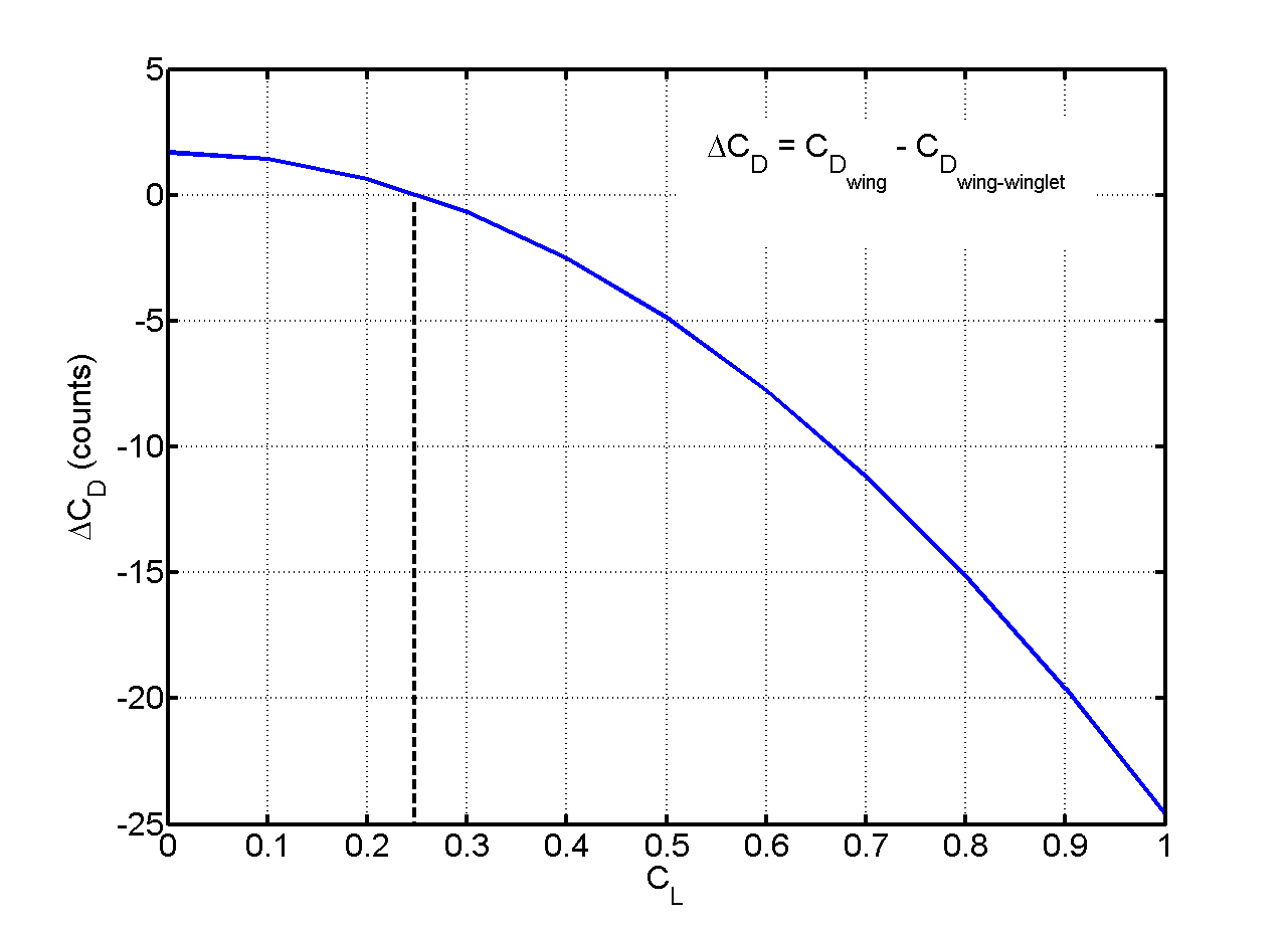
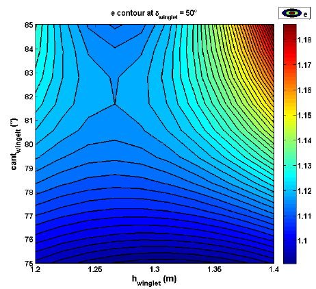
Several analysis has been carried out in order to improve the wing induced drag factor, and the results on the optimized winglet are
here presented. The optimized winglet shape could be defined as a semi-blended winglet with an height about the 10%
of the wing semi span, a cant angle of about 80 degrees and a sweep angle of about 50 degrees. The designed winglet
allows an improvement of the wing induced drag factor of about 11% with respect to a reference wing with the same aspect ratio.
Most of the commercial long-range aircraft are equipped with winglet to decrease the induced drag thus saving more
fuel; this feature can also be found on birds, but in conventional aircraft, the winglet device is fixed. Recent projects point
toward advanced smart materials and telescopic wing-tip devices to obtain an adaptive morphing shape that gives,
through performances improvement, a fuel consumption and so a pollutant reduction. In order to obtain pollution
reductions via high aerodynamic efficiency, the design of a telescopic inflatable variable height wing-tip device has been
addressed. The span variation is pursued toward a telescopic device that is linked to an inflatable system distributed in
chord and along the base of tip, ready to be extruded according to flight conditions. The performance analysis has been
conducted especially to evaluate range performance, which mainly provides the relation to fuel consumption.
The hinged telescopic device gives the chance of obtaining variation in winglet span according to flight condition requirements in
terms of stability and aerodynamic efficiency. The solution of the inflatable system would guarantee a more comfortable
arrangement of deployment system and just minor surplus of weight compared to classical winglet solutions, with all the
subsequent advantages. A representation of this device is shown in the following figures and videos.
