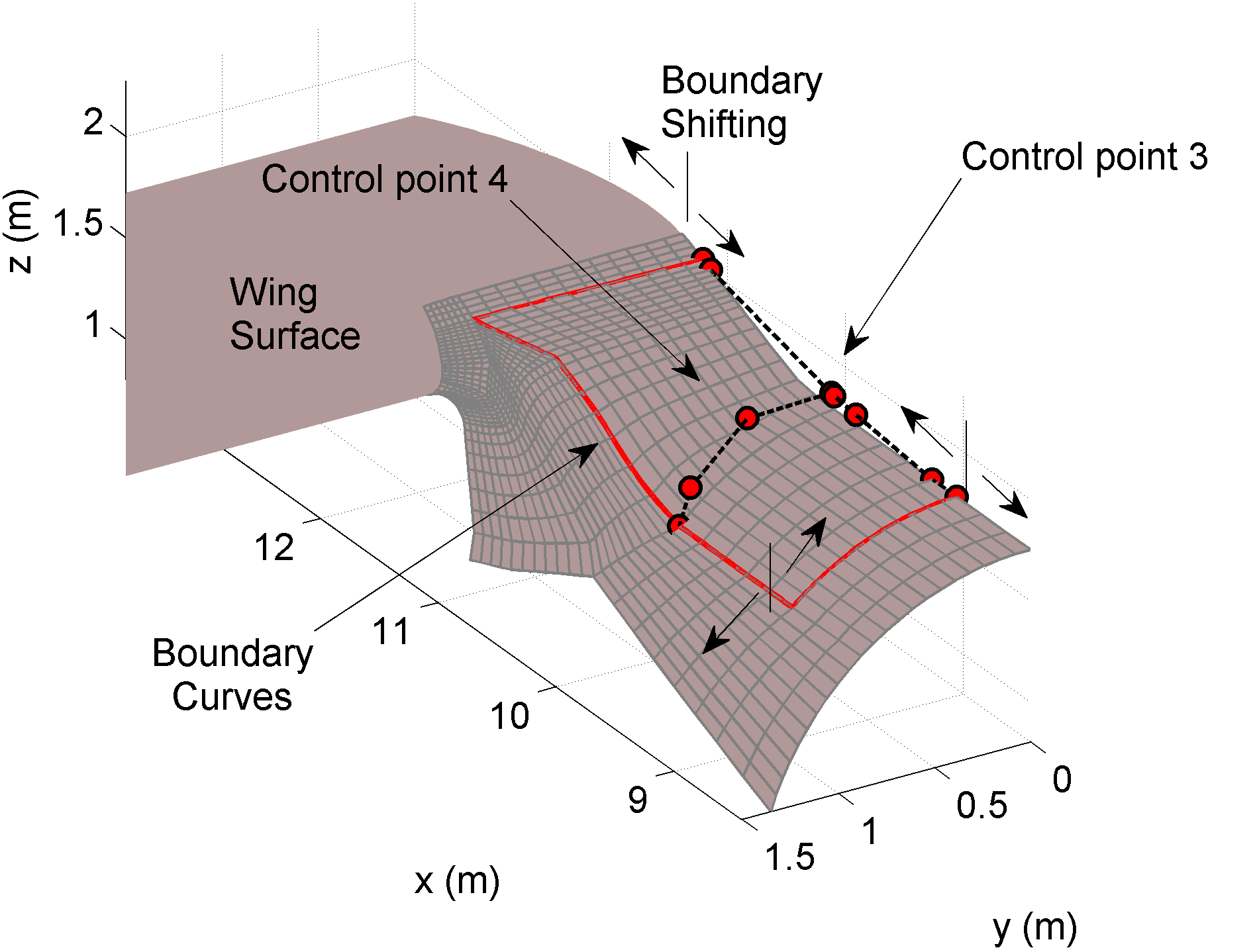
Some particular aircraft components design and optimization have been analyzed: fuselage nose, wing-fuselage junction and undercarriage vane. An accurate design of these components can lead to non negligible improvements in aircraft performance and it could establish new aerodynamic guidelines in the design of modern aircraft models. A tool has been developed into MATLab environment which allows to import, optimize and export CAD useful file of a particular aircraft component. NURBS geometry technique has been implemented and used into the optimization loop, while an available three dimensional panel code aerodynamic solver has been used for the aerodynamic analysis to evaluate the objective function. Particular attention has been aimed to the effect of the optimization on the aircraft performance, highlighting improvements for level flight, climb and ground performance.
In order to check the panel code aerodynamic optimization results,
two Reynolds Average Navier-Stokes (RANS) aerodynamic analyses have been performed,
the first on the wing-body geometry with the original karman component,
the other on the wing-body geometry with the optimized karman (see Figures below).
The software used in the RANS simulations has been the commercial CFD software Star-CCM+.
The optimized geometry leads to a drag reduction of about 3.1 drag counts in cruise condition
and 5.6 drag counts in climb condition. The main effect of the karman component optimization
is related to the pressure drag reduction, while the friction drag increase of about 1 drag count.
The optimized karman wetted area is greater than the original one and it covers a portion of the
original fuselage surface both forward and rearward.
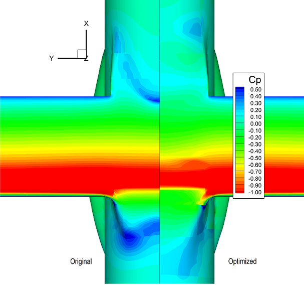
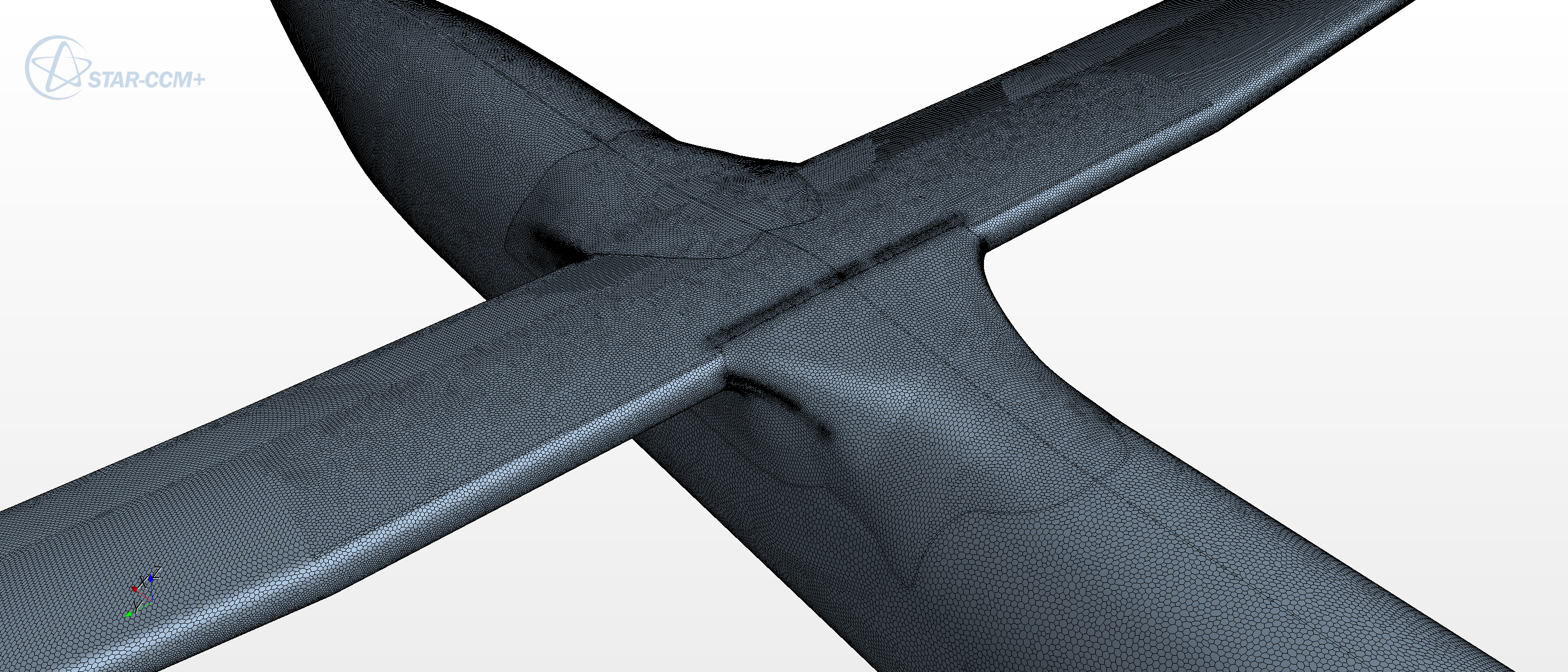
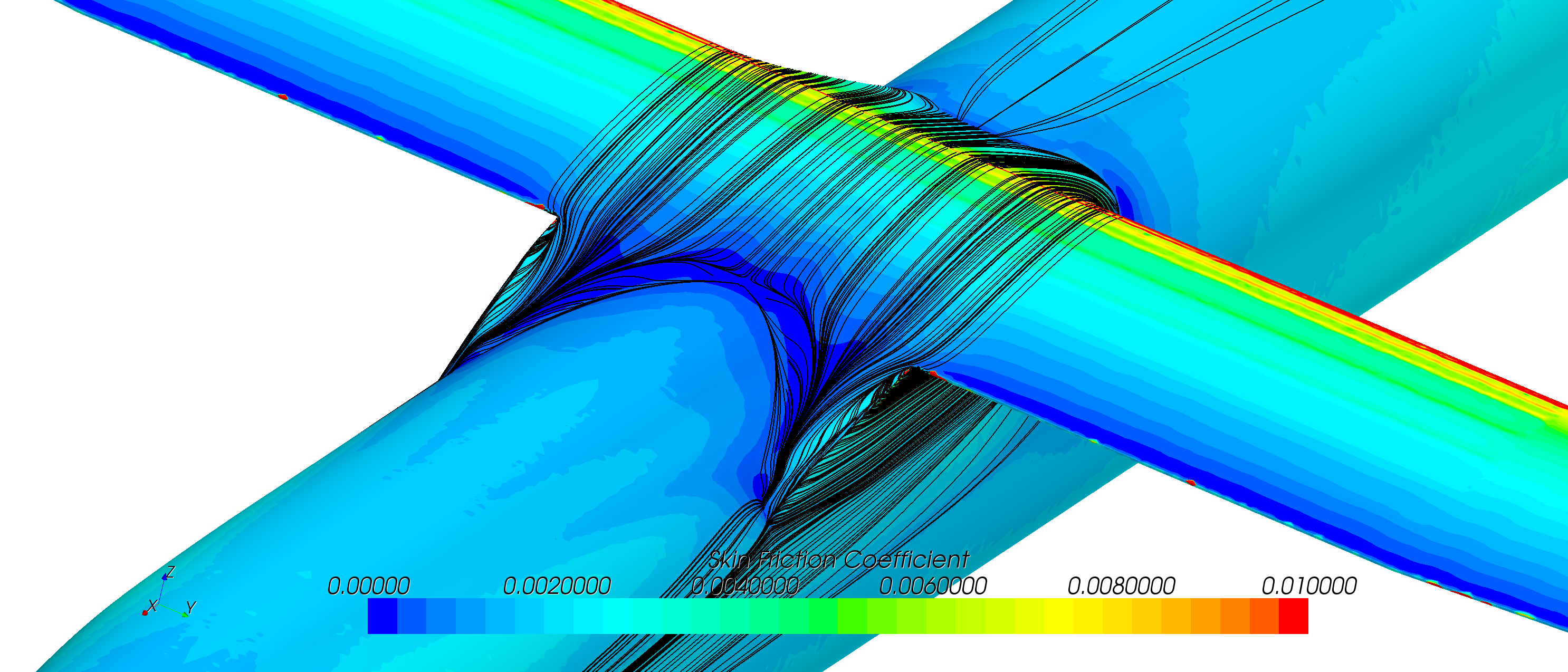
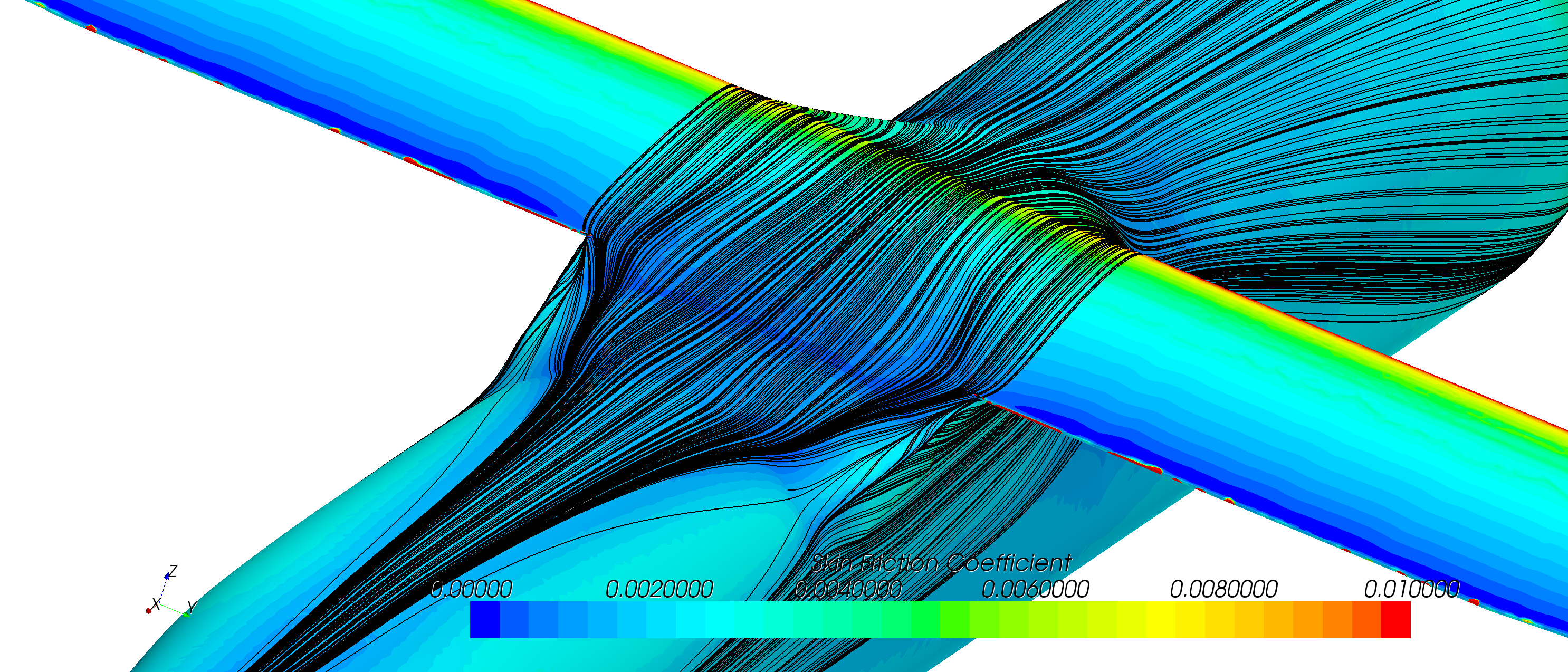
Figures provide isometric views of the wing-boby-karman geometries looking
from above the aircraft nose for the original and optimized kamarn, respectively, in climb condition.
The surface skin friction coefficient are provided with a color map where
dark blue indicates separation flow (Cf = 0.0), and bright red shows accelerated flow (Cf = 0.01).
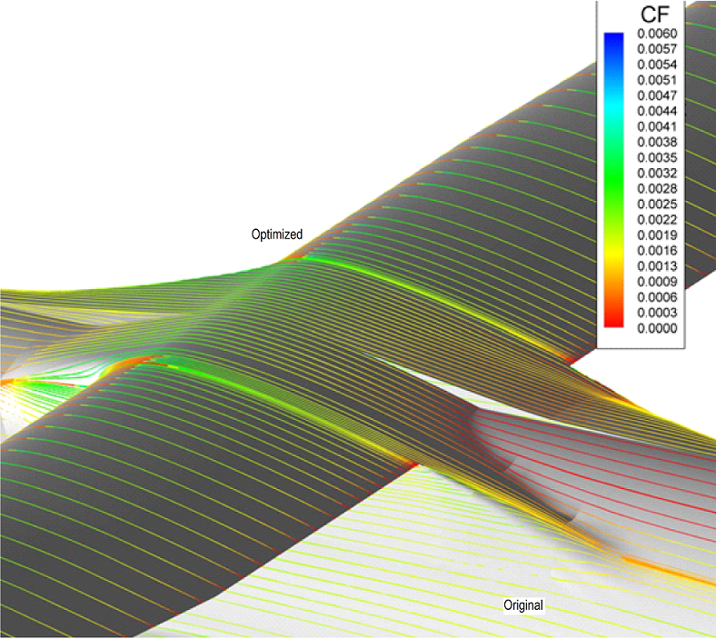
The “surface” constrained streamlines depicted in these figures are actually streamlines confined to a computational plane located
just off the no-slip surface. They are traced only starting from the karman components and then they can also go on
the other components until separation is reached.
Figures also illustrates the large separation zone of the original wing-body geometry configuration.
This image also confirms that both on forward and backward fuselage-karman intersections
skin friction coefficient goes to zero. Conversely on the optimized geometry constrained streamlines are traced also on the fuselage, confirming no more flow separation on the fuselage-karman intersection.
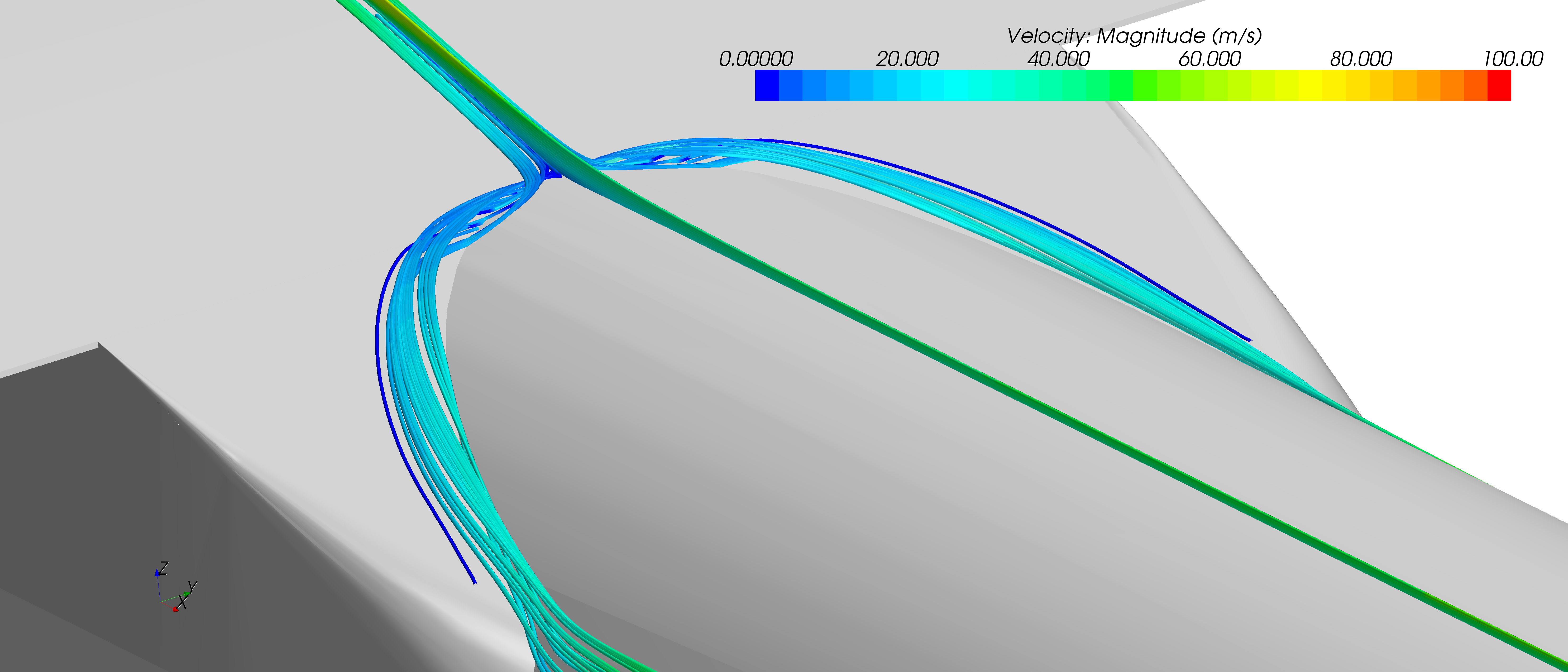
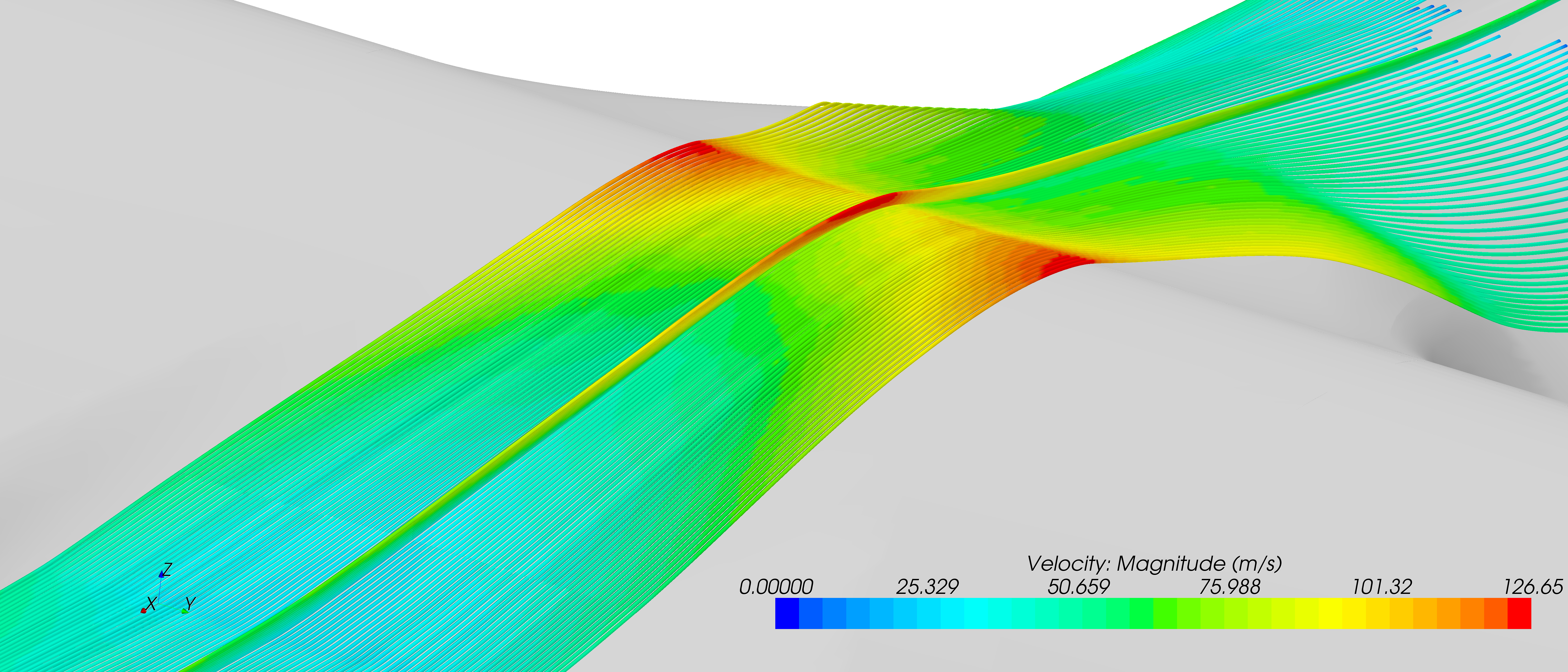
Figure below shows the off body streamlines traced in correspondence of the corner between fuselage
and karman components. As it can be seen in the original geometry there is a spanwise flow introduced
by this corner and a separation zone just before the corner. In the optimized karman geometry,
the higher smooth shape allows the flow to stream along undisturbed flow direction without any hint of separation.
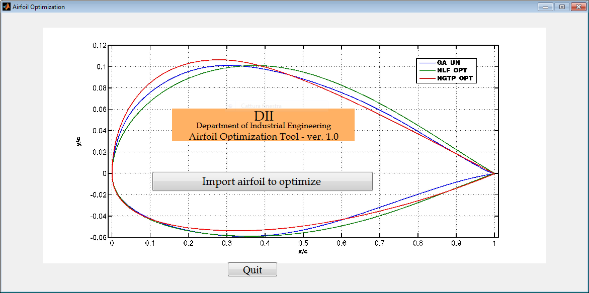
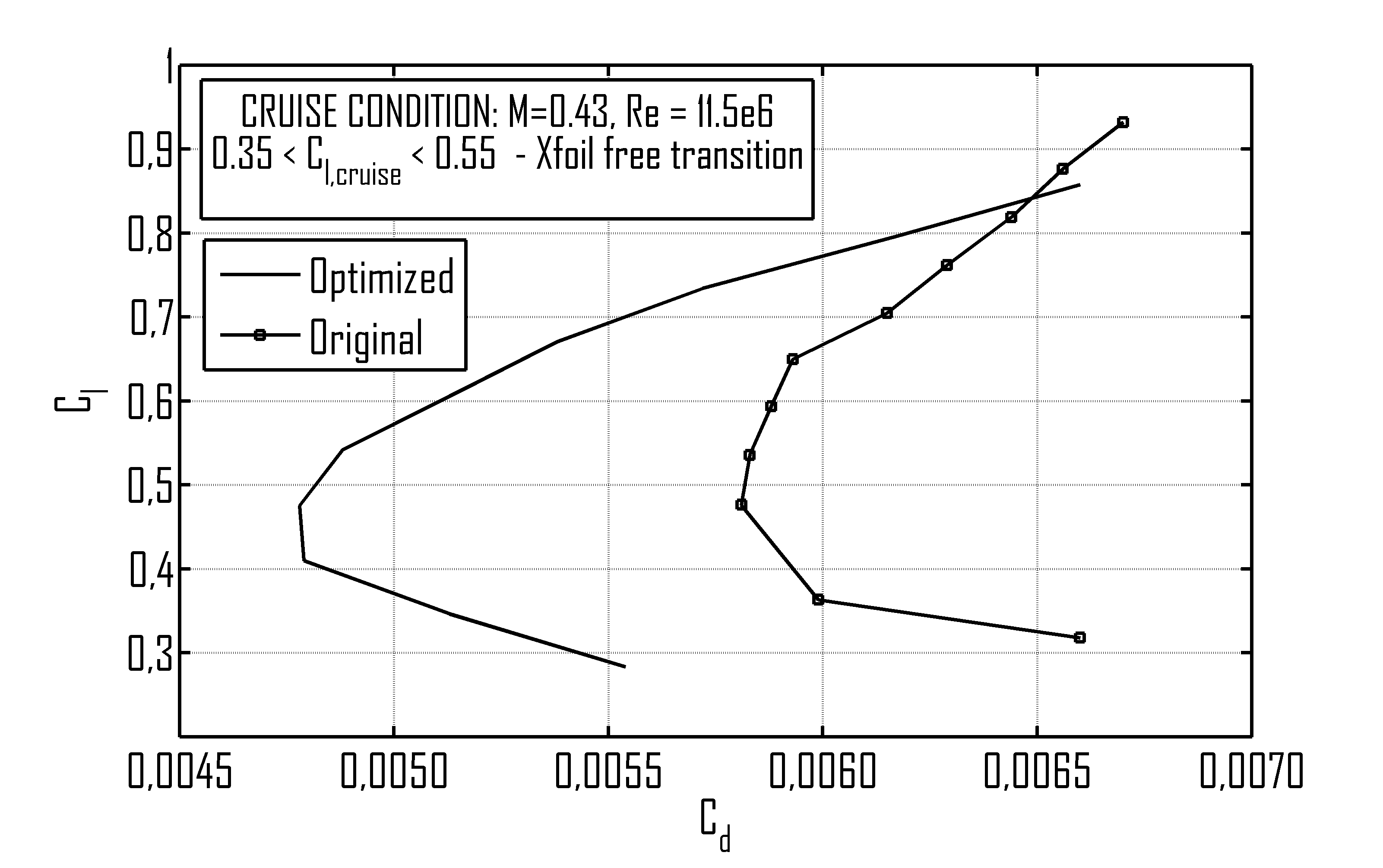
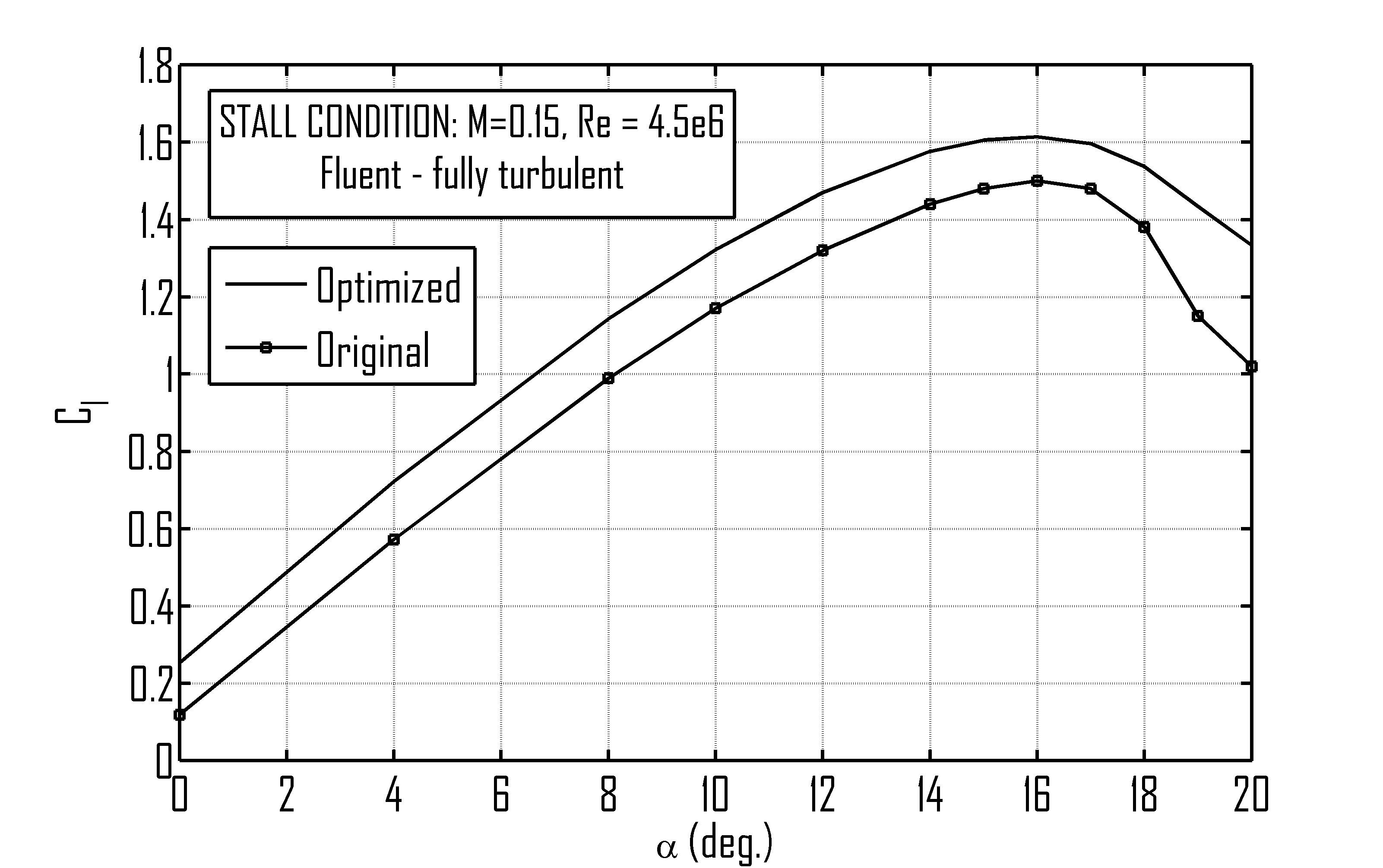
The development of an airfoil optimization tool, named AOT, has been carried out.
This tool is fully embedded into MATLab environment and it can easily managed via graphical interface (GUI) or via input text file.
The AOT allows the constrained multi-objectives optimization of any airfoil geometry through three different aerodynamic solvers:
Xfoil, MSES and Fluent. Different geometry parameterization techniques are described and implemented,
highlighting the pros and cons of each ones and three optimization algorithm can be used in the process.
This tool has been extensively tested and used also for industrial applications and main results have been published into the PhD thesis.