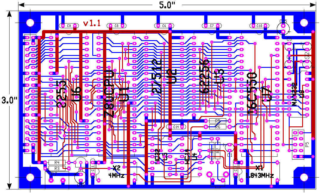
Z80 PCB
Here is an the PCB for a simple Z80 board made by Thomas Scherrer
this project is born from a thread on comp.os.cpm, only small variations are done by me:
Added a connector for PIA signals and INT, NMI from CPU
Added a transitor to connect INTR from SIO to INT of CPU
The reset pushbutton is one of that are monted on CDROM readers, 6x6 mm , vertical mount
The PCB is NOW COMPLETE
Found a BUG in previus release , please use this version 1.1,
16c550 require an active high reset pulse
the PCB is available here to receive feedback from potential users:
complete Bottom Top and Silk Images
blue tracks are on solder side ( BOTTOM )
red tracks are on component side ( TOP )
small tracks are 15 mils
fat tracks are 50 mils
vias are 50mils/15 mils ( pad/hole )
pads are 60/70/28 mils ( oval / hole )
most of track start from pads on solder side to facilitate mounting of socket on non metalized vias PCB
at this stage the PCB can be done by a fab , I don't know if is doable at home
( lack of experience )
Mounting holes are 3 mm in diameter good for screw , not good for plastic standing
On PCB:
P7 is the power supply connector ( 5 V regulated )
P6 is the parallel port expansione ( 8255 PIA )
P5 is the serial port ( TXD / RXD / DSR / DTR )
P1 is the reset push button
please send me your notes to this email address: m.colandrea@libero.it


